This post contains affiliate links, meaning I get a commission (at no additional cost to you) if you decide to make a purchase through my links. I only share affiliate links for things that: a) we have actually used (or comparable items if the original item is no longer available), b) that I would use again, and c) that I think would benefit your build. See my disclosure for more info.
Heating the Quonset Hut with Radiant Floor Heating
Radiant floor heat is going to be one of the creature comforts we’re building into the house and we’re really excited about it. Any time you have open, lofty space in a home, the most efficient way to heat it is via in-floor radiant heat, making it a great solution for heating a Quonset hut home. Blowing hot air around in a big lofty space is super inefficient as I’m sure you can imagine – the heat just rises up to the ceiling.
On the other hand, warming gently from below is not only more efficient, but it affords a greater degree of comfort overall. Warm feet lead to an overall greater feeling of warmth throughout the body, and radiant heat is less prone to feelings of draftiness as when the furnace kicks on and starts blowing the air around.
This post is largely about our system for recirculating the water through the tubing in our floor slab; for more detail on setting up the tubing and pouring the slab, see this post. Also, this post contains affiliate links, and you can read more about our affiliate link policy in our Terms of Use.
Basics of our System
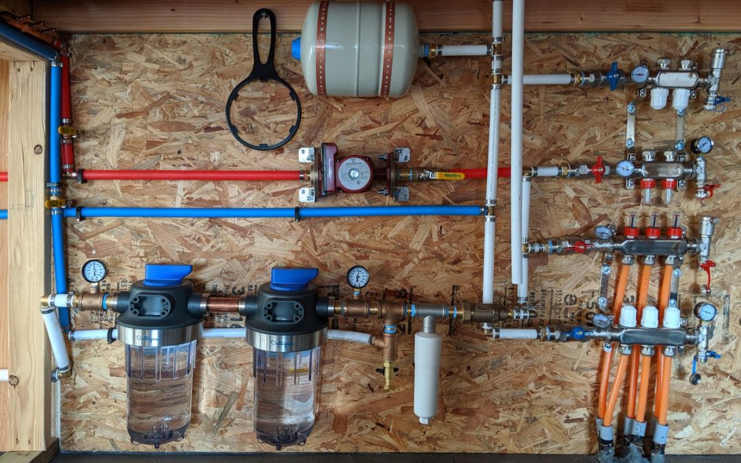
Here is a diagram of our system, followed by a step-by-step explanation keyed to the numbers; below the explanation are some closeups from different angles:
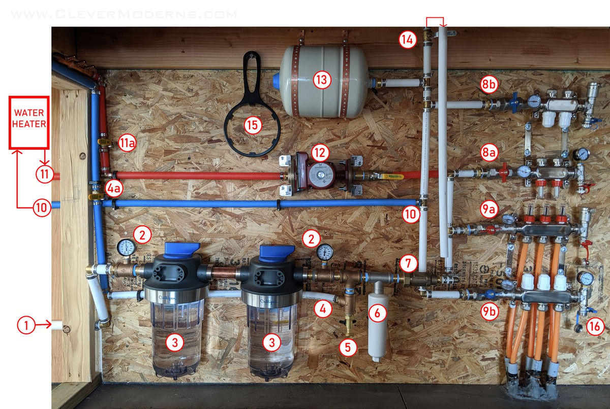
- Water enters the building. Just off the picture to the left is our main shutoff valve. See also Detail #1 below.
- Pressure gauges on either side of the filters. A noticeable pressure drop from one side to the other would be a sign it’s time to change the filters.
- Dual filter system (these are just the housings – the filter elements are not installed in them yet).
- This is a Tee that branches off to a manifold supplying the cold water to the house; on the left side of the image is a shutoff valve (4a) allowing us to completely turn off the cold water feeding the bathroom & kitchen.
- Hose bib which can act as a drain port if needed.
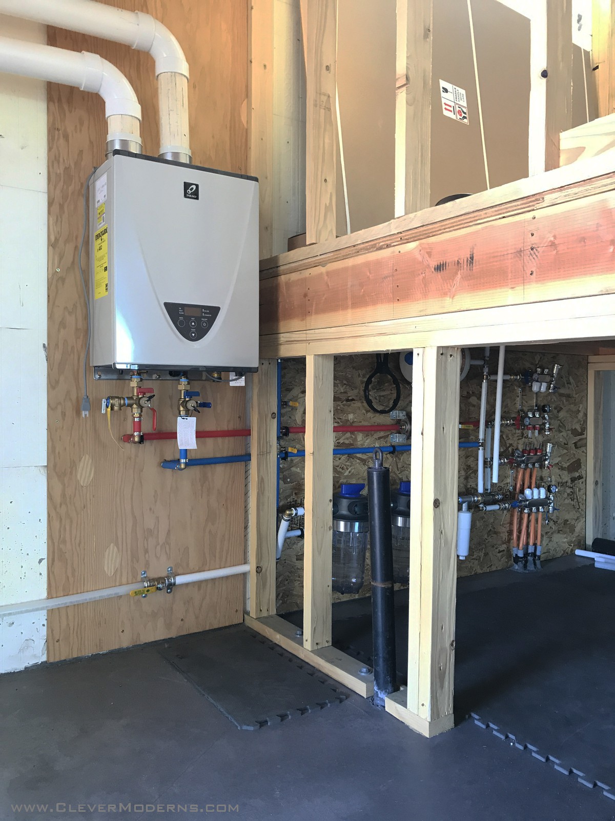
- Water scale inhibitor to help prolong the life of our tankless water heater.
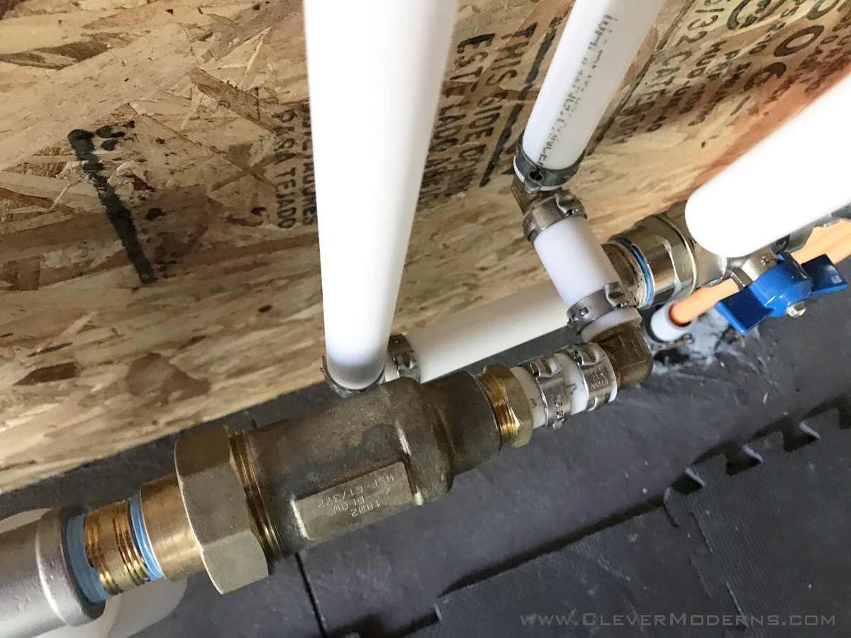
- Check valve aka back flow preventer (the white vertical line #10 passes behind this, see Detail #2 below).
- Two-loop manifold: (8a) will send hot water up into the bathroom and sitting area floors above, but this tubing is not installed yet. (8b) will be where the water will return from the above floors.
- Three-loop manifold: (9a) directs the water down through the orange tubing into the floor slab; (9b) is where the water returns from below.
- (8b) and (9b) join together at (10) and all the cold water returning from the floor(s) goes to the water heater.
- Hot water coming out of the water heater immediately branches off, and passing through shutoff valve (11a) goes to the manifold feeding the house.
- This is the pump that will be activated when the thermostat triggers “the air is too cold, send in more heat”. When the pump runs it pulls the hot water from the water heater and pumps it into the floor via (8a) and (9a).
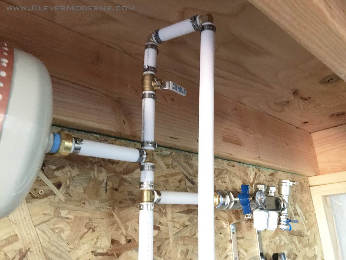
- Expansion tank to relieve extra pressure on the system induced by the water heater.
- This valve at the top of the system is located so as to trap air that could build up and cause trouble in the water heater and inefficiency in the system. By placing a bucket under the open end below, the valve can be opened and air purged from the system. See also Detail #4 below.
- This is a wrench to help remove the filter housing for filter installation/replacement.
- To further purge air out of the system, a short hose can be connected here to run to a small pump submerged in a bucket. With the bucket half filled with water, and placed under the open end of (14), the pump can then send water through the floor tubing thus driving out air when the open end of (14) dumps the water (and any incident air) back into the bucket.
The vertical white tube at far right is the open end of (14).
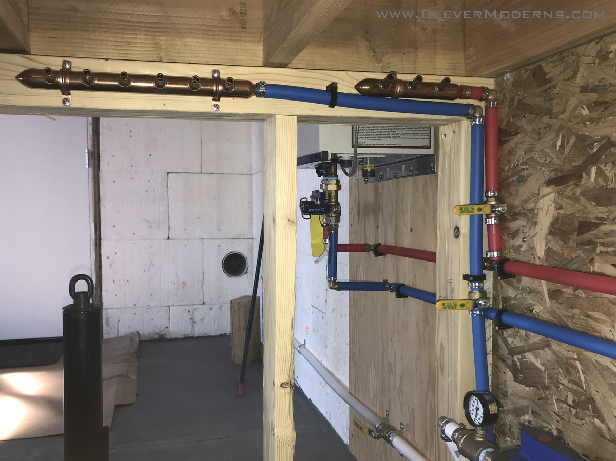
Shutoff valves (4a) and (11a) are at right center.
I hope this all makes sense and helps you understand our system!
What about in summer time?
If you find yourself asking “what about in summer time when you want a hot shower but you don’t want to heat your floor?” I invite you to look at the sequence above again, from that point of view. Here is what will happen:
Any time you turn on a faucet while the pump is not running, whether summer or winter, hot water will exit the water heater at (11) and immediately be pulled through valve (11a) and up into the house. As long as the pump is not running, this heated water will not be drawn through the floor. The standard water pressure in the system will simply draw fresh cold water through the floor to the water heater, and then on to the faucet or shower. This way, even in summer, the water in the floor is constantly cycled through the system and prevented from stagnating.
But whenever the pump is triggered, and only when it is pumping, it will pull water directly from the water heater and send it into the floor, then back through the water heater, repeating as needed, until the floor and consequently the air in the room are sufficiently warmed.
A Few Additional Tips
Some things that might be useful that aren’t pointed out specifically above:
- If you’ve done any plumbing work yourself, you’ve probably used thin white teflon tape to help seal up threaded connections. This blue thread seal tape is a far better choice, and is heavier than the flimsy thin white tape. A little more expensive but it has saved us tremendous time and trouble since we discovered it.
- Pex tubing: beware that Wirsbo and PEX are not the same! They look very similar but the parts are not interchangeable. Be cautious if you’re in a hurry at the hardware store.
- Our manifolds for the floor tubing (items 8a/b and 9a/b) were purchased on Amazon, but the ones we got don’t seem to be available any more, and we don’t have a good suggestion to link to for those right now. If we become aware of a good option for manifolds we’ll update this post; meanwhile I suggest inquiring at a local plumbing supply.
And, lastly, if you want to see how we set up the tubing before we poured our slab, you can revisit this post from last fall.
As always, I invite your questions in the comments. Thanks for reading!
Curious about Quonsets? Ready to learn more about these bizarre, amazing, shiny, round, prefab structures? Drop your info below and I’ll start you off on my email tutorial series. Looking to build an inexpensive but beautiful home debt-free? Considering going off-grid? Or are you just tired of the same old same old and want something unique and beautiful? A Quonset House might be the answer for you.
Follow us on Instagram and Facebook. We also have a private Facebook group called DIY Quonset Dwellers, where we share discussion, design, and construction tips with others who are interested in building their own Quonset hut house. With over 6,000 members and counting, the Facebook group has grown into an amazing resource all of its own! Learn more and request to join the Facebook group here.
Hello, I am installing infloor heat and am using your component diagram. I am thinking a check valve is also needed after the circulation pump to avoid cold water being mixed in with hot water when its used for showers ect. Do you have any issues with cold water flowing backwards through the circulation pump? Thanks Jim
Hi Jim, our pump has a built in check valve, so no need to add one.
I understand using water for a system in a home. What are your thoughts using glycol in a work shop setting, i.e., a facility that doesn’t have an associated plumbing system that also sits vacant at times?
I’ll be honest that I’m not the best person to ask that. We did enough research to do our project but I’m no expert on radiant heating systems in a wider context, or on glycol systems. I would say it’s definitely worth looking into though! Could be a good thing.